Fourth Assignment - High(er) voltage and transistors!
Circuit


Creating a schematic, circuit, and code that uses a transistor to control load power separate from logic power. You have to use analogWrite(), a high-load output device, and an input sensor
Schematic
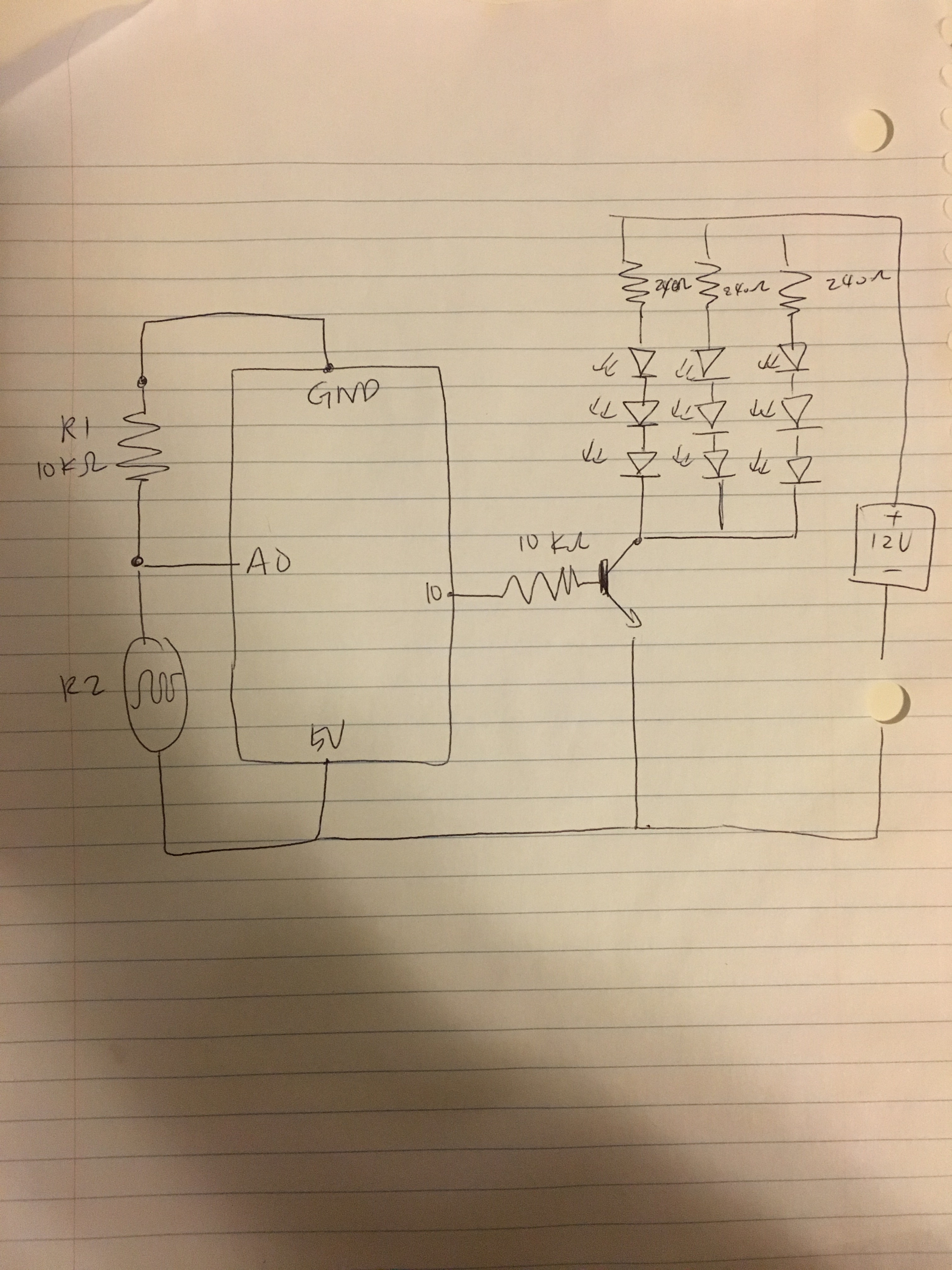
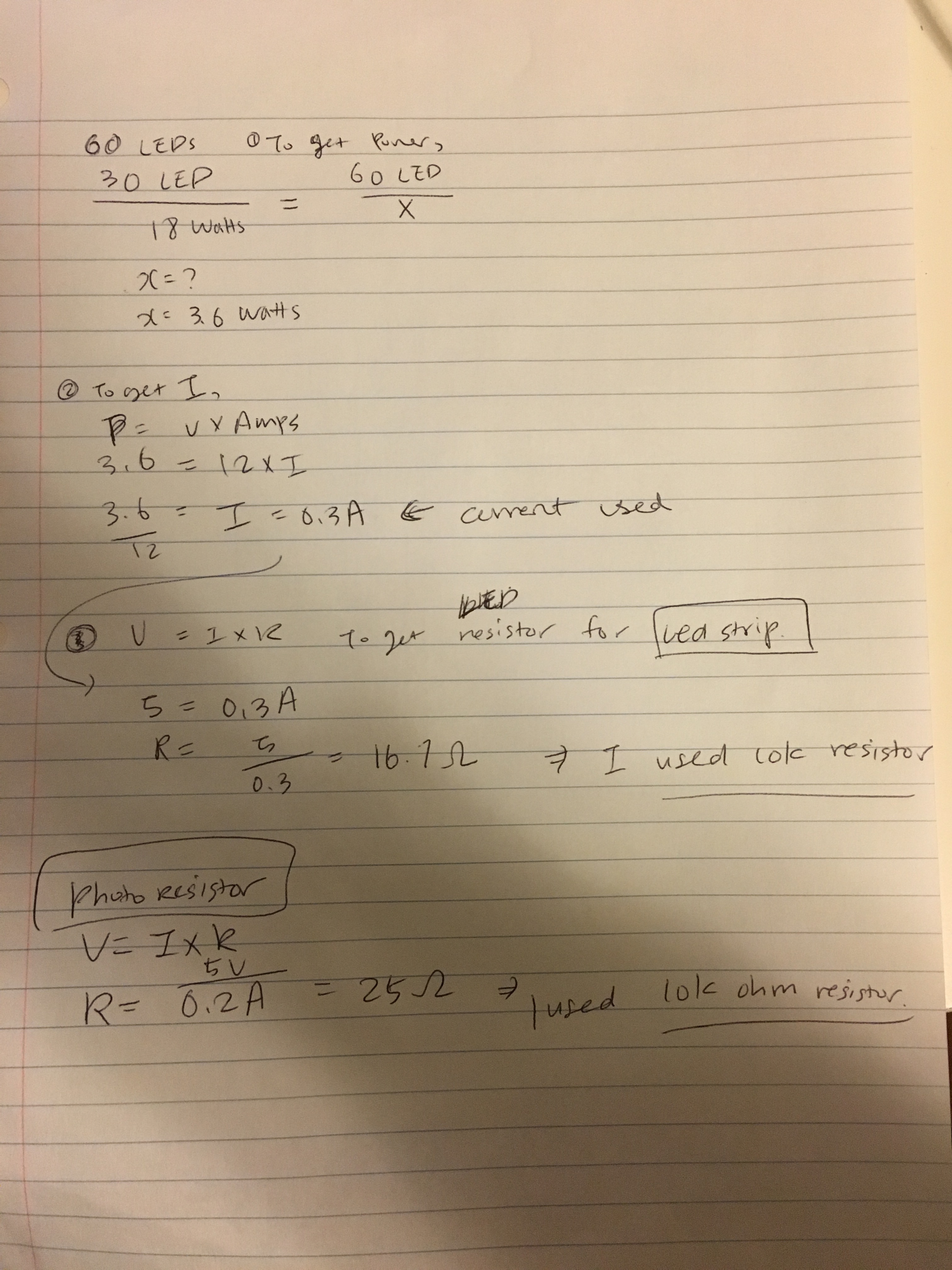
Calculation
Firmware
//set pin numbers
const int ledPin = 10; //the number of the lED pin
const int ldrPin = A0; //the number of the LDR pin

int sensorValue = 0; // value read from the photoresistor
int outputValue = 0; // value output that is mapped out

void setup() {
    // initialize serial communications at 9600 bps:
    Serial.begin(9600);
    //initialize the LED pin as an output
    pinMode(ledPin, OUTPUT);
    //initialize the LDR pin as an output
    pinMode(ldrPin, INPUT);
}

void loop() {
    // read the ldrLED in value
    sensorValue = analogRead(ldrPin);
    //map it to range of analog out
    outputValue = map(sensorValue, 0, 1023, 0, 255);

     // When output value is equal to or less than 200, turn the LED on
    if (sensorValue <= 200) {
      // turn on LED
      digitalWrite(ledPin, HIGH);
      Serial.println("LED is ON");

    // if the output value is greater than to 200, turn the LED off
    } else {
      // turn off LED
      analogWrite(ledPin, 0);
      Serial.println("LED is OFF");
    }
}
Circuit's operation

Tada! Once covering the area and minimizing exposed light near photoresister, this beautiful LED strip turns on!