Third Assignment - Input Output!
Circuit
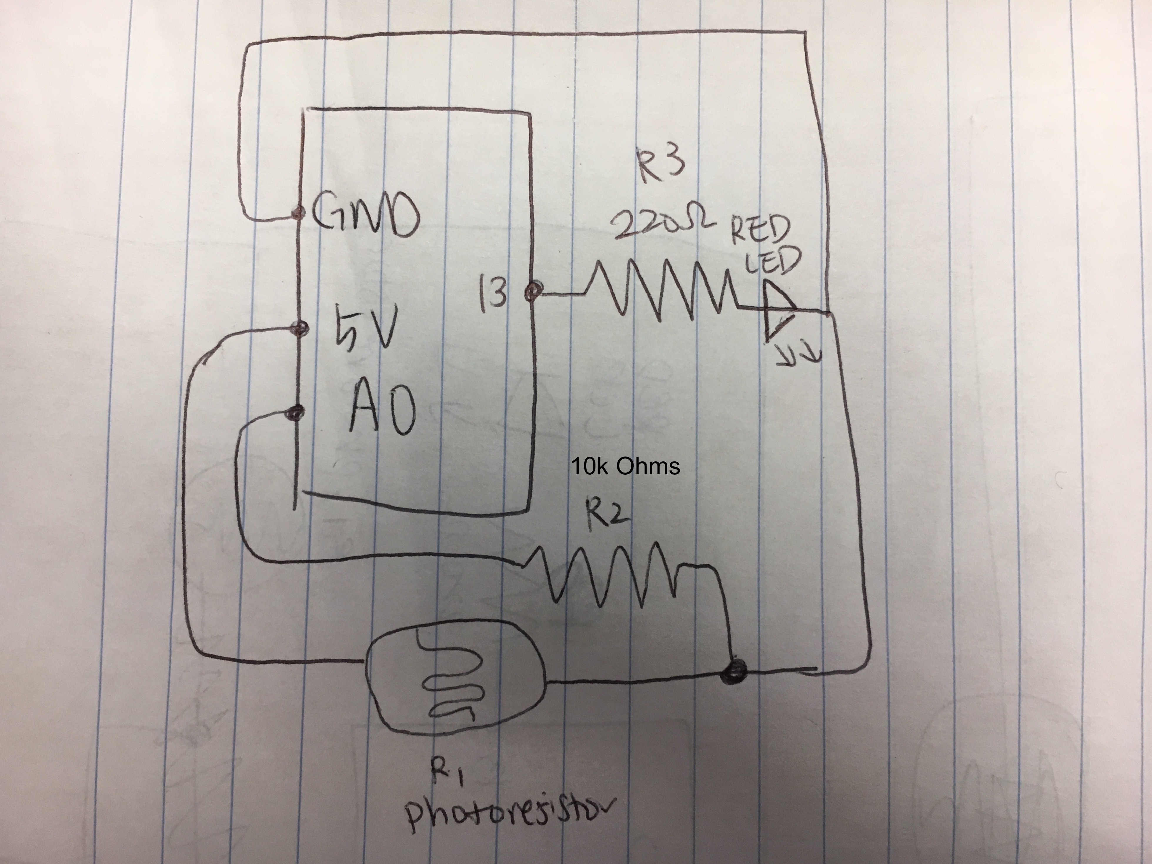
Creating a schematic, circuit, and code that uses a sensor (e.g. either the photoresistor or the thermistor) in a voltage divider to change the state of an LED.

Schematic
Calculation
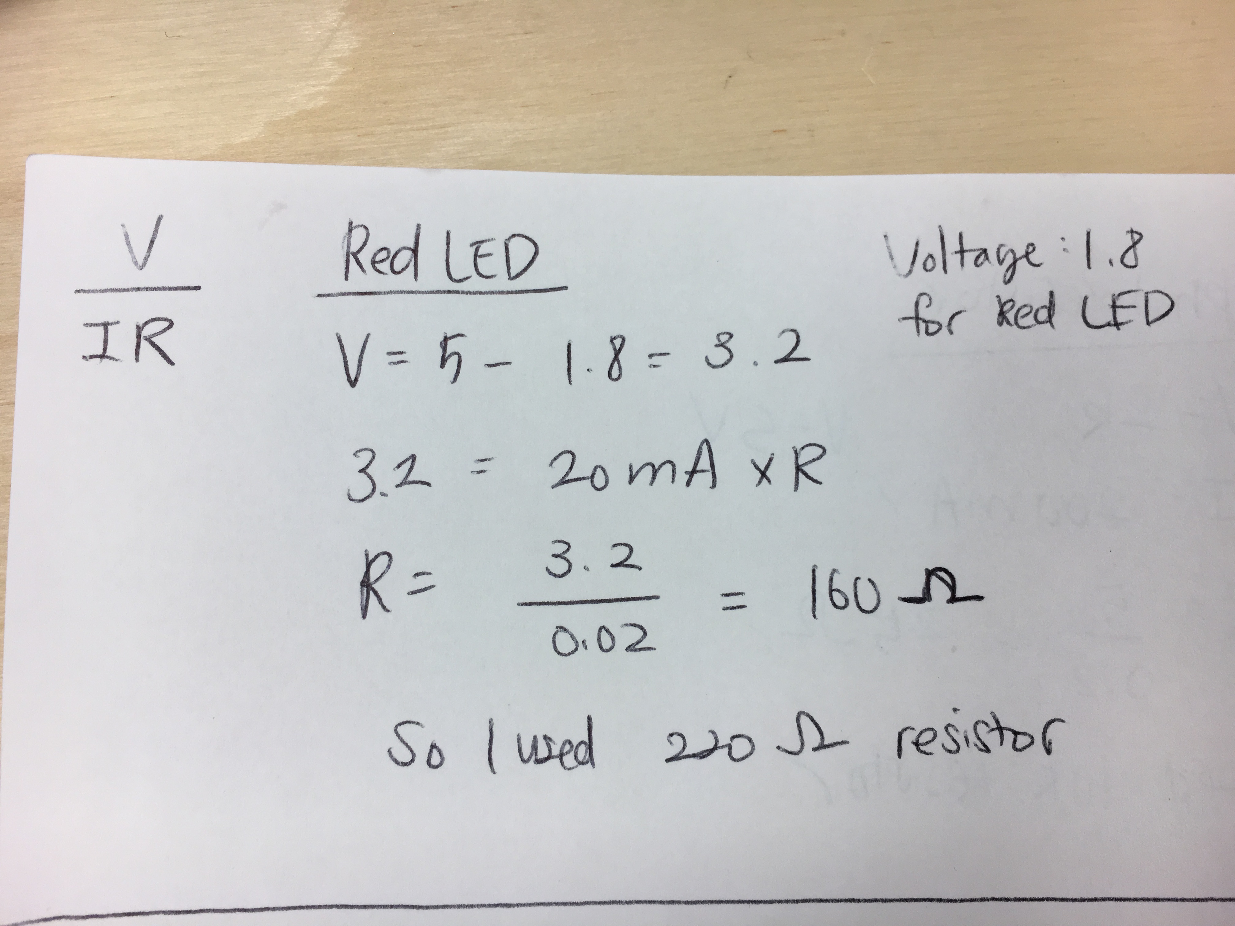
LED Resistor
I chose 220Ω for the resistors for my LED because I needed to find the optimal resistor to prevent broken LEDs. The reasoning is -- red LED has 1.8 V drop. Current is 20 mA. Voltage from Arduino is 5V. Using Ohm’s law(V = I x R), the circulation to find R is:5V - 1.8V = 3.2 V = 0.02 (20mA) x R. R is 160Ω. And the resistor nearest value to 160Ω was 220Ω.
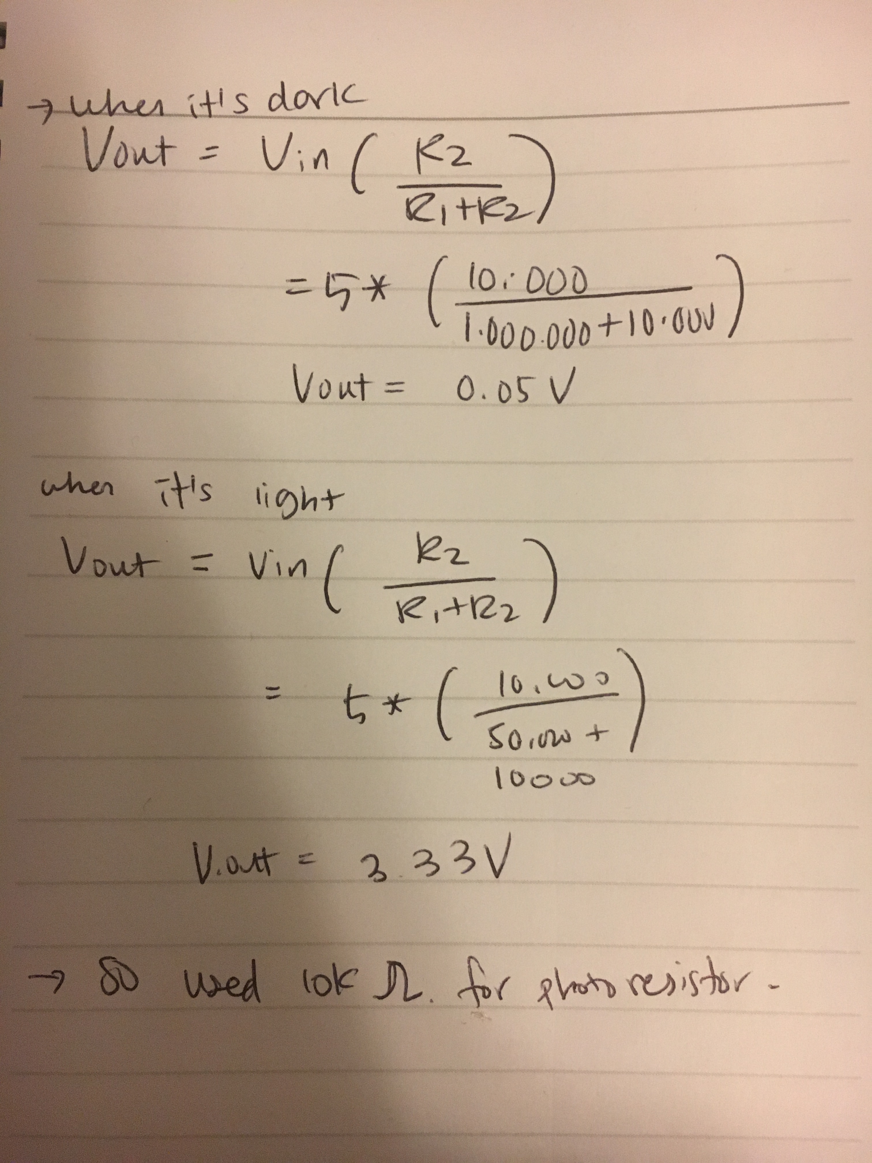
Photoresistor Resistor
Firmware
//set pin numbers
const int ledPin = 13; //the number of the lED pin
const int ldrPin = A0; //the number of the LDR pin

void setup() {
    // initialize serial communications at 9600 bps:
    Serial.begin(9600);
    //initialize the LED pin as an output
    pinMode(ledPin, OUTPUT);
    //initialize the LDR pin as an output
    pinMode(ldrPin, INPUT);
}

void loop() {
    // read the ldrLED in value
    int sensorValue = analogRead(ldrPin);
    //map it to range of analog out
    int outputValue = map(sensorValue, 0, 1023, 0, 255);

    // if the output value is greater than or equal to 200, turn the LED on
    if (outputValue <= 200) {
      // turn on LED
      analogWrite(ledPin, 220);
      // write to the serial monitor that the LED is on
      Serial.println("LED is on");
      // When output value is equal to or less than 200, turn the LED off
    } else {
      // turn off LED
      digitalWrite(ledPin, LOW);
       // write to the serial monitor that the LED is off
      Serial.println("LED is off");
    }
}
Circuit's operation

Tada! Once covering the area and minimizing exposed light near photoresister, the red LED turns on!